

Designing your own Case
It's your turn!
Now that we've learned some of the fundamentals of our base Toober and developed some basic understanding of CAD, we have the opportunity to build on and explore these skills as we design our own case for our Toobers toy!
Use the tools in this tutorial (or any others you may come across) and make modifications to your copy of the base Toobers design, showcasing your uniqueness and interests! There is no right or wrong way to start or finish this process - just make sure you're proud of the end result.
We will be 3D-printing your designs in the coming weeks.
Base Constraints
- In the base model, all the walls are around 3mm thick. Typically, it is good to maintain at least 2.5mm thickness on large wall sections.
- You may modify the button locations in the top piece, but please do not change the placement of components in the bottom piece or change the openings for the battery or power switch in the bottom piece. These are the hard points.
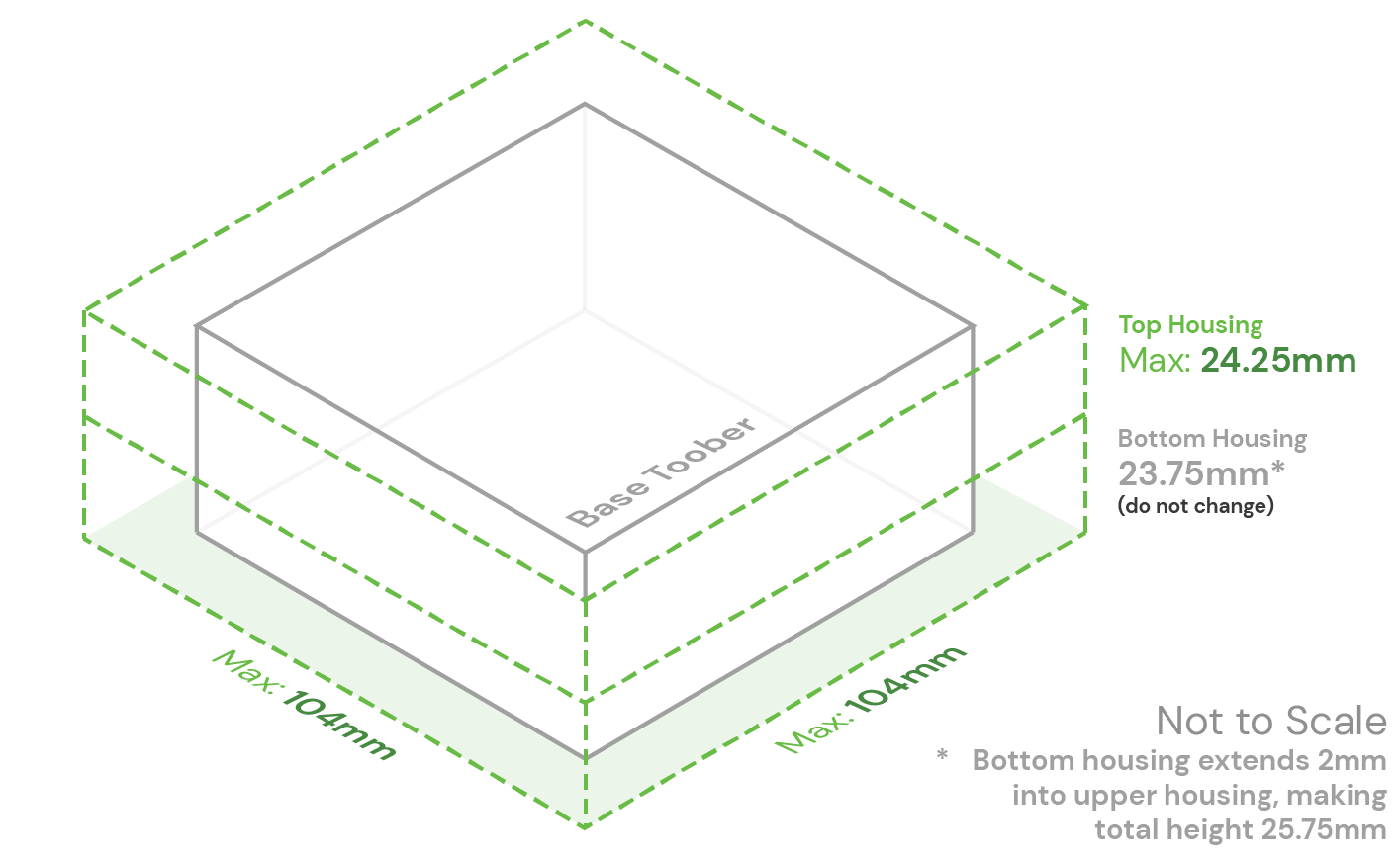
- For additions onto the body, they may not increase the overall length or width of the top or bottom piece by more than 14mm in the X or Y direction. One way to think of this is to keep your design within 7mm from all sides, but the available 14mm buffer can be split along each axis in whichever manner you wish.
- The top housing may have up to a 7mm increase in overall height.
- The bottom housing may not change in height.
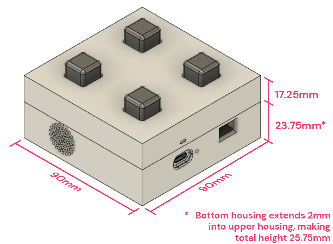
The image below contains dimensions of the existing base toober.
The green lines in the image below represents the bounding box to which your design can extend. Think of all the possibilities!
Additional Appendages and ProTOOBERances
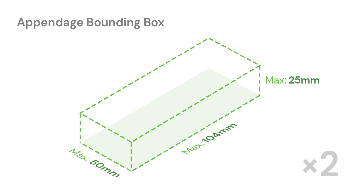
You may design appendages that go on any of the faces that protrudes outside of than the allotted bounding box, but we will be printing them separately and then you will join them to the base cube shape. All such appendages should not be larger than 104 x 50 x 25 mm each. If your design requires more than 2 such appendages or additional printing capacity, please contact the TAs on #ask-the-tas to discuss your design, which will need to be approved.
Leave your appendages on your model. The 3D printing staff will carefully slice them up and add the necessary pins to join the pieces together, being mindful of locating features as well as strength of printed part. You will receive plenty of instructions and glue during the assembly party.
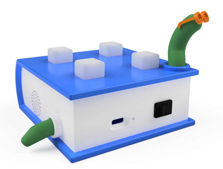
Below is an example of a Toober with an appendage. It's our textbook example bookworm, Professor Wigglesworth.
Submission Instructions
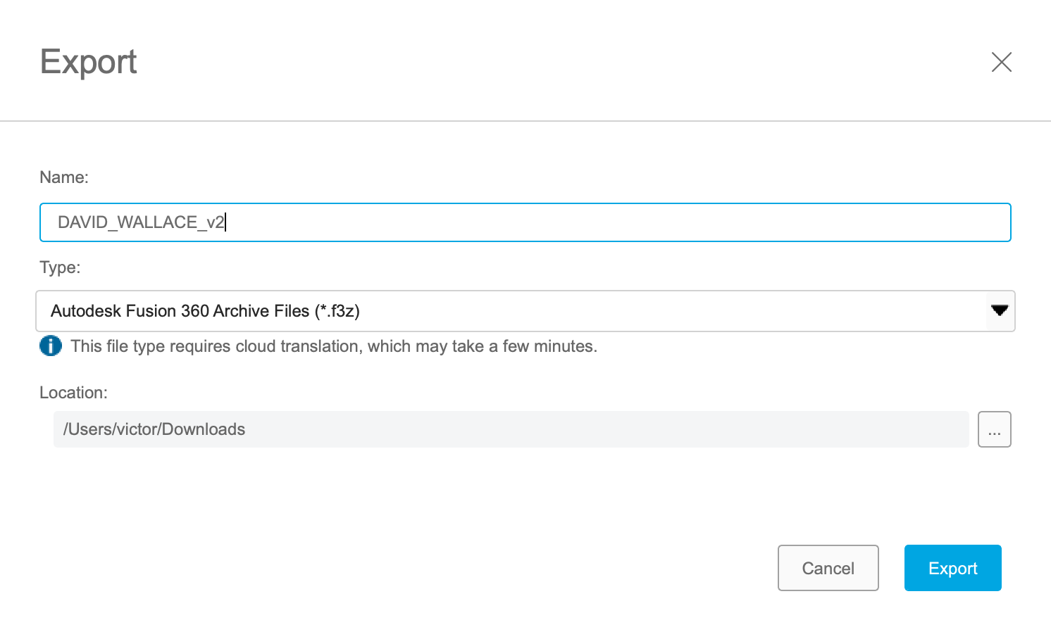
To submit your custom Toobers enclosure, please post all your submission items in the #3d-print Slack channel the following files in 1 thread:
.f3zof your assembly namedFIRSTNAME_LASTNAME_v[X].f3z.- YOUR_NAME should be in UPPERCASE
- Separted by underscores
- The v should be in lowercase
- The [X] should be the version number of your saved Fusion 360 save file, without the square brackets)
DAVID_WALLACE_v2.f3znote the underscore and Your name should be in UPPERCASE. The v should be lowercase.- Two screenshots showing your design (from different angles, so we know what it is supposed to look like)
- The Toober Submission Text Details template (copy and paste the block of text below, changing the text to describe your Toober)
- Decal image files. Decal images should be ideally 300 PPI, and should be clearly named
- Fonts used in your design. If you used a font that is not a standard font, please include the font file in your submission.
Toober Submission Text Details
Follow the template below and replace the text below with details of your submission, and then copy and paste it into your Slack post. Please provide all dimensions in mm. Fusion 360 has a bunch of tools to help you measure.
Exporting your File
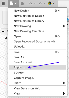
Toober housings will be printed roughly in order of submission date. Please submit your case design as soon as you are finished and happy with it so that we can start printing before the submission deadline. Changes cannot be made to your case once we have started printing it!
Submission Checklist. Before you Submit!
Please carefully review this list and check off all items before submitting! Ensuring that you've done these checks will help us reduce errors and save time in your printing process.