

The Base Model Features
Secrets about our Base Model
The base model contains a bunch of exciting features that you are free to snatch up for your future toy designs! We don't expect you to recreate any of these, but this hopefully gives you some insight into what we've included in your base Toober! Additionally, when you submit your Toober, please make sure these features aren't accidentally removed/altered!
Alignment Features
The Toober base model has a couple of simple alignment features. One such feature is a physical break in the continuity of the parting line of the bottom shell as seen below. The Toober top shell has a matching protrusion that locates perfectly into the base shell, made with the Fusion 360 boolean operation. This feature ensures that the Toober case can only be assembled together in one orientation, which is important in keeping the sugar cube buttons mapped correctly to the PCB.

The reason we need this internal alignment feature is because we want the screws to always line up, and for the button mappings to be consistent to the PCB below.
As the first alignment feature is an internal alignment feature not visible on the external surfaces, it is accompanied by a second external alignment feature that can be seen in the image below. The pill shape on the side of the top shell serves as a visual indicator of correct orientation.

Certain Toober designs, such as the Textbook Example doesn't need a visual indicator like this because the top and bottom housing orientation is clear.

USB Port
The USB-C charging port feature needs to provide both access to the USB charging circuit as well as provide enough clearance around it for the USB plug to be fully inserted into the charging circuit without any interference from the surrounding Toober shell wall. The shell wall is cut out around the USB port in this wall to ensure the molding around the USB plug does not collide with the case.

Wire Clip
The wire clip feature is an extrusion from the sidewall to assist in cable management for the speaker.

Housing Screws
The top and bottom case parts are secured together with two housing screws. The housing screws pass through the screw boss features of the bottom shell and screw into the threaded inserts installed in the top Toober shell as seen below.

PCB Mounting Features
The PCB mounting features highlighted in red demonstrates one technique to locate the PCB in the housing using the mounting holes in the corners of the board, while also providing a shoulder for the board to rest on high enough above the case bottom to accommodate the double sided tape that secures the board to the case.
The PCB mounting feature highlighted in blue demonstrates another technique to locate and elevate the PCB without the use of an existing hole feature on the board.
The PCB mounting feature highlighted in yellow is similar to the feature highlighted in blue but it accommodates the asymmetry of the PCB board, preventing assembly in the wrong orientation.

Sugar Cube Mounting Points
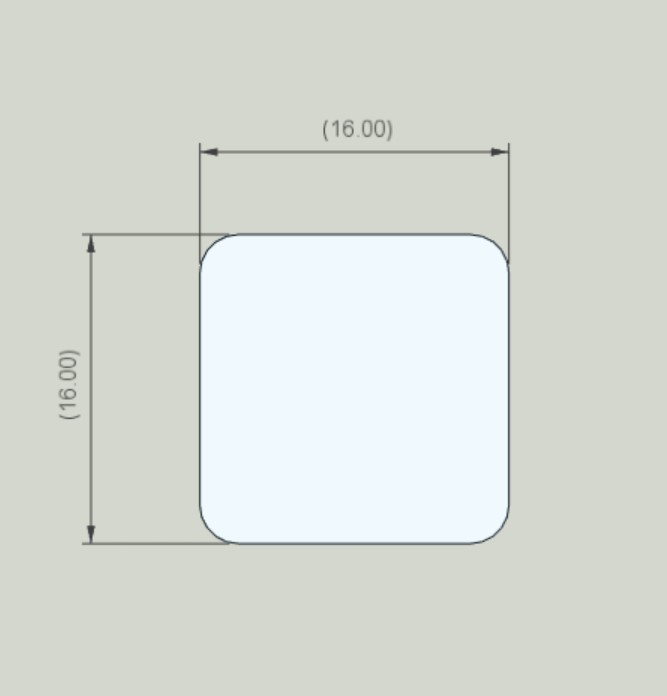
The sugar cube buttons require a few key modeling features. First the button cut out in the shell wall itself, which should be 16 x 16 mm.

Highlighted in yellow on the inside of the Toober, the top of the case is slightly inset (0.3 mm) around the button cutouts to provide extra clearance for the screw heads that assemble the button to its circuit board and acrylic mounting plate, as well as a visual reference which marks roughly the area taken up by the PCB and acrylic mounting plate.
Highlighted in red are two screw boss features that can accommodate threaded inserts for mounting the sugar cube assembly to the Toober case. A 1mm chamfer helps increase the strength of the part around the screw boss features.
Acrylic Light Channel Mount
Near the USB-C opening is a feature attached to the side wall which can hold a small piece of acrylic. The hole for this is counterbored such that a screw head sits flush with the surface as the diameter of the M3 screw head is smaller than the major (larger) hole diameter, and the primary hole (smaller) can accomodate a threaded insert. The M3 screw then clamps down onto the acrylic, holding the acrylic in place.

The purpose of the small sliver of acrylic is to direct light from the charging module (which shows red when charging, and green when charged) to the outside of the case. A tiny hole just to the right of the USB-C opening allows enough light to pass through such that the user can see if the device is charging, not charging, or completed charging without having to open the Toober housing.
Here is a photo of the acrylic on top of the charging module, with the red charging indicator on.

And here is a photo of it from the outside, what the toy user would see!
